
Break the quality deadlock of refractory bricks
author: XINTAI
2025-08-21
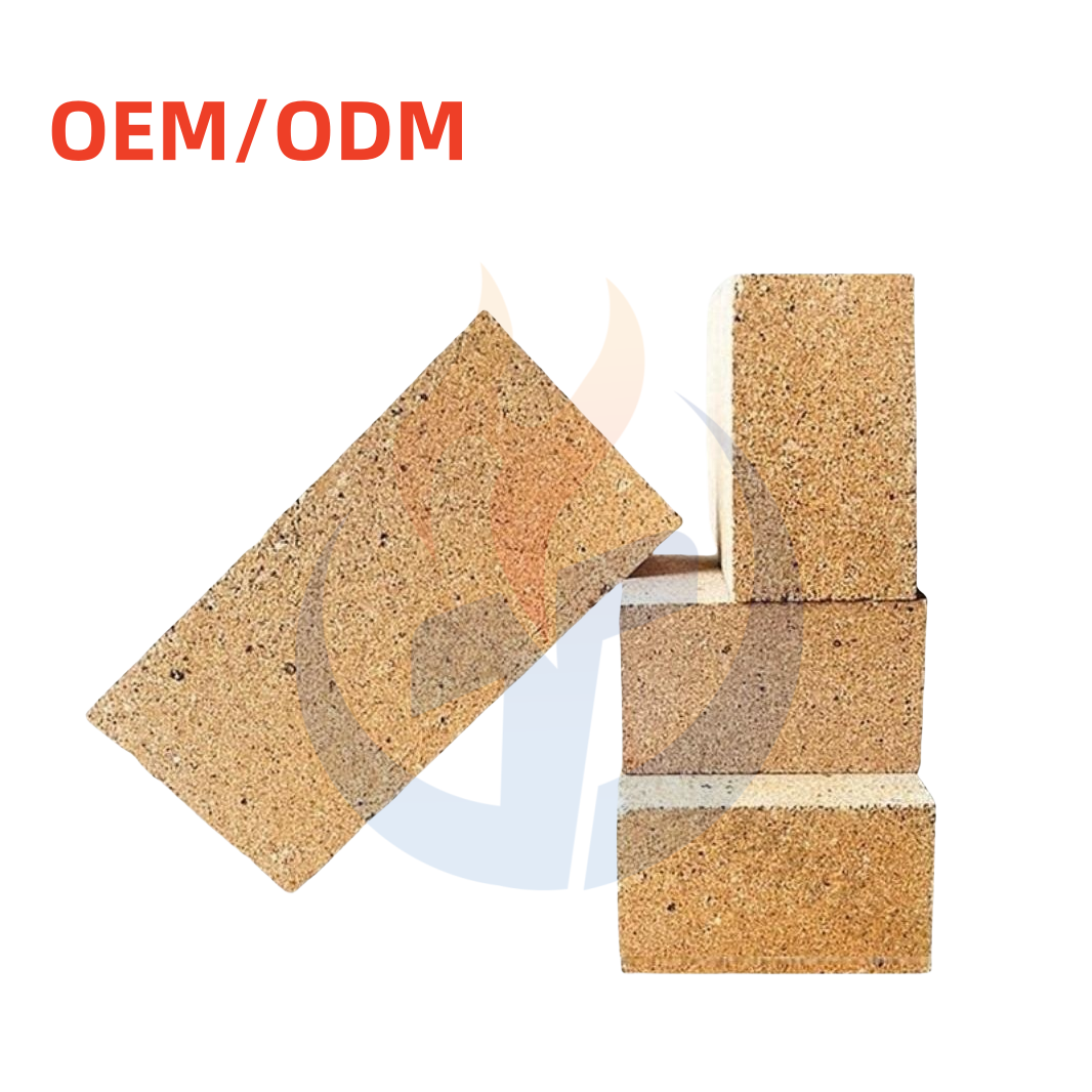
As the saying goes, "A workman must first sharpen his tools if he is to do his job well." If refractory material manufacturers want to effectively reduce the defective rate of refractory bricks, it is recommended to start from the detection methods first, trace the causes from the results, discover the reasons for the defects of refractory bricks, and then solve them.
01. Dimensional inspection
1. Dimensional inspection shall be carried out in accordance with the provisions of the order drawing.
2.When measuring, the zero point of the steel ruler must be aligned with the edge of the product. Steel tape measures and steel straightedges can be selected. When measuring the inner and outer diameters of products, use a tool caliper.
3. For general products (unless otherwise specified), the dimensions of the middle one-third of each side of the product shall be measured as the standard.
4. The measurement of the opposite sides of the product shall be based on the difference between the two opposite sides of the same size of the product. The measurement of the relative edge difference between the male and female diameters of the product shall be based on the difference between the long and short shafts on the same male or female opening of the product.
1. Dimensional inspection shall be carried out in accordance with the provisions of the order drawing.
2.When measuring, the zero point of the steel ruler must be aligned with the edge of the product. Steel tape measures and steel straightedges can be selected. When measuring the inner and outer diameters of products, use a tool caliper.
3. For general products (unless otherwise specified), the dimensions of the middle one-third of each side of the product shall be measured as the standard.
4. The measurement of the opposite sides of the product shall be based on the difference between the two opposite sides of the same size of the product. The measurement of the relative edge difference between the male and female diameters of the product shall be based on the difference between the long and short shafts on the same male or female opening of the product.
02. Inspection of molten holes
1.When inspecting the melt hole, it is allowed to first gently tap the surface of the product with a small metal hammer to remove the melting voids and significant discolored areas caused by low-melting substances, and then measure the maximum diameter of the melt hole with a steel ruler.
2. Voids caused by external organic inclusions such as wood chips, oil sludge, and fabric chips shall also be inspected in accordance with the inspection method for melt holes, but the allowable value shall not exceed one times the value of the melt hole in the product (for example, if the value of the melt hole is specified as 8mm, then the value of the void shall not exceed 16mm).
1.When inspecting the melt hole, it is allowed to first gently tap the surface of the product with a small metal hammer to remove the melting voids and significant discolored areas caused by low-melting substances, and then measure the maximum diameter of the melt hole with a steel ruler.
2. Voids caused by external organic inclusions such as wood chips, oil sludge, and fabric chips shall also be inspected in accordance with the inspection method for melt holes, but the allowable value shall not exceed one times the value of the melt hole in the product (for example, if the value of the melt hole is specified as 8mm, then the value of the void shall not exceed 16mm).
03. Inspection of missing corners and edges
1. The inspection of the depth of missing corners and edges should be carried out using specially manufactured Angle gauges and edge gauges that can be tightly fitted onto the edges and corners of the product and are equipped with a scale that can slide in the specified direction.
2. For right-angled products, the depth of the missing corner should be measured using a cubic goniometer along the diagonal direction of the center of the cube. For non-right-angled products, use a Mitsubishi body goniometer to measure along the centerline direction of the Mitsubishi body.
3. The depth of the missing edge is measured along the direction of the equal division line of the Angle between the two sides of the product to determine the deepest point of the missing edge. For those with length restrictions, measure the full length of the missing edge simultaneously.
4. When missing corners or edges are connected, check them separately. The missing edges of the missing corners are not counted as missing edges. That is, the missing corners are inspected in accordance with the regulations for missing corners, and the missing edges are inspected in accordance with the regulations for missing edges.
5. Unless otherwise specified, all missing corners and edges with a depth greater than 3mm to the allowable limit of the standard shall be included in the calculation. Missing corners and edges with a depth of 3mm or less are not regarded as missing corners or edges.
1. The inspection of the depth of missing corners and edges should be carried out using specially manufactured Angle gauges and edge gauges that can be tightly fitted onto the edges and corners of the product and are equipped with a scale that can slide in the specified direction.
2. For right-angled products, the depth of the missing corner should be measured using a cubic goniometer along the diagonal direction of the center of the cube. For non-right-angled products, use a Mitsubishi body goniometer to measure along the centerline direction of the Mitsubishi body.
3. The depth of the missing edge is measured along the direction of the equal division line of the Angle between the two sides of the product to determine the deepest point of the missing edge. For those with length restrictions, measure the full length of the missing edge simultaneously.
4. When missing corners or edges are connected, check them separately. The missing edges of the missing corners are not counted as missing edges. That is, the missing corners are inspected in accordance with the regulations for missing corners, and the missing edges are inspected in accordance with the regulations for missing edges.
5. Unless otherwise specified, all missing corners and edges with a depth greater than 3mm to the allowable limit of the standard shall be included in the calculation. Missing corners and edges with a depth of 3mm or less are not regarded as missing corners or edges.
04. Inspection of Cracks
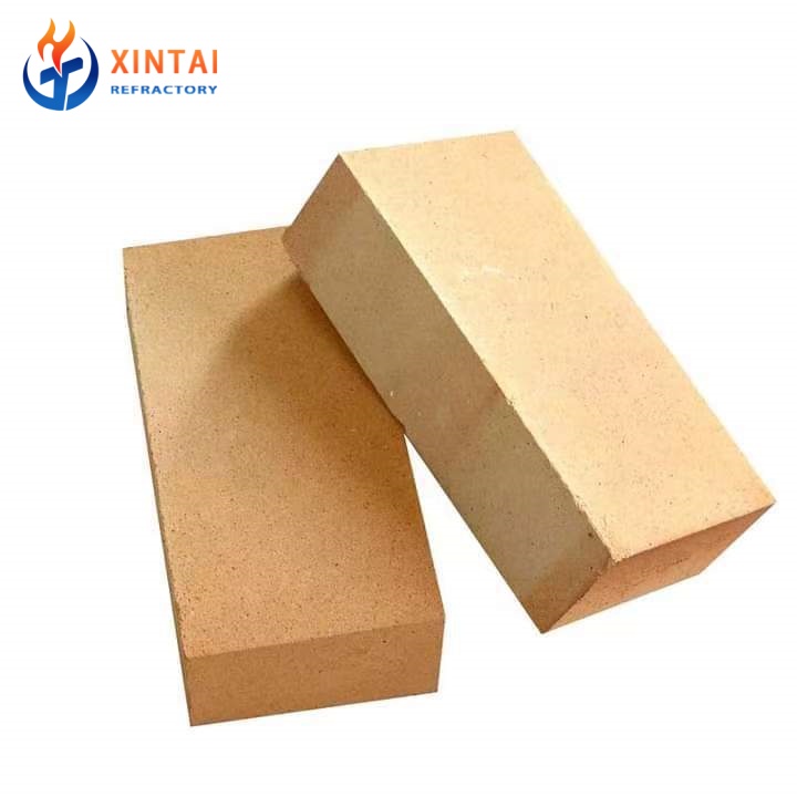
1. Crack inspection: Use a steel ruler with a scale up to 0.5mm and steel wire with a diameter equal to the crack width (for example, 0.1, 0.25, 0.5, 1.0mm).
2. When checking the crack, insert the steel wire into the widest part of the crack naturally, but do not insert the visible particle drop. For cracks where 0.25mm steel wire cannot be inserted, the width is indicated as less than 0.25mm. For cracks where 0.25mm steel wire can be inserted but 0.5mm steel wire cannot, the width is expressed as 0.26 to 0.5mm. And so on.
3. If the crack is not in a straight line, it can be measured by scoring line segments. The sum of the lengths of each line segment is the total length of the crack. Cracks with breaks in the middle and the distance between the breaks greater than 5mm (including unrestricted cracks) are regarded as one crack, and their lengths are combined for calculation, except for cracks in the crossing and parallel directions.
4. For cracks spanning ridges, unless otherwise specified, they shall all be calculated based on the continuous length. If a crack spans both the working surface and the non-working surface simultaneously, it shall be evaluated based on the working surface (for example, according to a certain standard, for cracks with a width of 0.26 to 0.5mm, the working surface should not exceed 30mm and the non-working surface should not exceed 50mm). If the crack spans both the working surface and the non-working surface simultaneously, the continuous length should be evaluated based on the working surface and should not exceed 30mm. Cracks that span two edges at the corner and do not exceed the specified value range of the missing corner shall not be calculated as spanning two edges. All cracks that are not restricted as stipulated in the standards are not subject to the restrictions of crossing edges and are not subject to inspection.
5. Surfaces with grooves or tongues shall be counted as one surface, except for bricks used for casting. Surfaces with through holes are counted as two surfaces.
6. Fine and long cracks formed due to improper cooling are classified as rapid cooling cracks (explosion cracks) and should be treated as non-conforming products.
7. When several cracks form a closed curve, it is called a network crack. When calculating the length of a reticular crack, the total length of the periphery is taken as the standard. When more than one crack intersects, it is called a cross crack. When calculating the number of cross-cracks, the straight-line cracks passing through the intersection points are mainly used.
8. Edges with an Angle greater than 120° are not counted as edges, and surfaces with a width less than 20mm are not counted as surfaces, except for bricks used for casting.
1. Crack inspection: Use a steel ruler with a scale up to 0.5mm and steel wire with a diameter equal to the crack width (for example, 0.1, 0.25, 0.5, 1.0mm).
2. When checking the crack, insert the steel wire into the widest part of the crack naturally, but do not insert the visible particle drop. For cracks where 0.25mm steel wire cannot be inserted, the width is indicated as less than 0.25mm. For cracks where 0.25mm steel wire can be inserted but 0.5mm steel wire cannot, the width is expressed as 0.26 to 0.5mm. And so on.
3. If the crack is not in a straight line, it can be measured by scoring line segments. The sum of the lengths of each line segment is the total length of the crack. Cracks with breaks in the middle and the distance between the breaks greater than 5mm (including unrestricted cracks) are regarded as one crack, and their lengths are combined for calculation, except for cracks in the crossing and parallel directions.
4. For cracks spanning ridges, unless otherwise specified, they shall all be calculated based on the continuous length. If a crack spans both the working surface and the non-working surface simultaneously, it shall be evaluated based on the working surface (for example, according to a certain standard, for cracks with a width of 0.26 to 0.5mm, the working surface should not exceed 30mm and the non-working surface should not exceed 50mm). If the crack spans both the working surface and the non-working surface simultaneously, the continuous length should be evaluated based on the working surface and should not exceed 30mm. Cracks that span two edges at the corner and do not exceed the specified value range of the missing corner shall not be calculated as spanning two edges. All cracks that are not restricted as stipulated in the standards are not subject to the restrictions of crossing edges and are not subject to inspection.
5. Surfaces with grooves or tongues shall be counted as one surface, except for bricks used for casting. Surfaces with through holes are counted as two surfaces.
6. Fine and long cracks formed due to improper cooling are classified as rapid cooling cracks (explosion cracks) and should be treated as non-conforming products.
7. When several cracks form a closed curve, it is called a network crack. When calculating the length of a reticular crack, the total length of the periphery is taken as the standard. When more than one crack intersects, it is called a cross crack. When calculating the number of cross-cracks, the straight-line cracks passing through the intersection points are mainly used.
8. Edges with an Angle greater than 120° are not counted as edges, and surfaces with a width less than 20mm are not counted as surfaces, except for bricks used for casting.
05. Inspection of distortion
1. Check with a feeler gauge made of a twisted metal sheet. The width of the feeler gauge is 10mm, and its thickness is 0.1mm greater than the allowable limit specified by the standard (for example: 1.6mm, 2.1mm, 2.6mm, 3.1mm, 3.6mm, etc.).
2. When checking for distortion, place the inspected surface of the product on a flat plate (the area of this plate should be larger than the inspected surface of the product), and keep it natural and stable. Then, smoothly insert the feeler gauge along the plate surface into the maximum gap formed between the plate and the product. A feeler gauge with an insertion depth not exceeding 10mm is considered qualified.
3. The indentation should be inspected by the twisting method.
1. Check with a feeler gauge made of a twisted metal sheet. The width of the feeler gauge is 10mm, and its thickness is 0.1mm greater than the allowable limit specified by the standard (for example: 1.6mm, 2.1mm, 2.6mm, 3.1mm, 3.6mm, etc.).
2. When checking for distortion, place the inspected surface of the product on a flat plate (the area of this plate should be larger than the inspected surface of the product), and keep it natural and stable. Then, smoothly insert the feeler gauge along the plate surface into the maximum gap formed between the plate and the product. A feeler gauge with an insertion depth not exceeding 10mm is considered qualified.
3. The indentation should be inspected by the twisting method.
06. Inspection of the tilt of the end plane
1.For the inspection of the tilt of the end plane, use a right-angle steel ruler with a side length of 220mm*220mm and a metal feeler gauge with a width of 5mm and a thickness 0.1mm greater than the allowable limit specified by the standard (for example, when checking the tilt of the 2.0mm end plane, use a feeler gauge with a thickness of 2.1mm).
2. When inspecting, make sure one side of the right-angle steel ruler is in close contact with the longitudinal surface of the product, while the other side is pressed against the end. Then, smoothly insert the feeler gauge along the gap formed between the right-angle steel ruler and the end. If the feeler gauge cannot be inserted as specified, it is considered qualified.
1.For the inspection of the tilt of the end plane, use a right-angle steel ruler with a side length of 220mm*220mm and a metal feeler gauge with a width of 5mm and a thickness 0.1mm greater than the allowable limit specified by the standard (for example, when checking the tilt of the 2.0mm end plane, use a feeler gauge with a thickness of 2.1mm).
2. When inspecting, make sure one side of the right-angle steel ruler is in close contact with the longitudinal surface of the product, while the other side is pressed against the end. Then, smoothly insert the feeler gauge along the gap formed between the right-angle steel ruler and the end. If the feeler gauge cannot be inserted as specified, it is considered qualified.
07. Inspection of slag erosion
1. Any glassy deposits formed due to the ash from the fuel adhering to the surface of the product during firing; The melting and discolored substances that occur when the surface of the product is eroded due to chemical changes between other impurities and the surface of the product are collectively referred to as slag erosion.
2. Products that have been processed and ground flat without obvious pitting or erosion are not counted as slag erosion.
1. Any glassy deposits formed due to the ash from the fuel adhering to the surface of the product during firing; The melting and discolored substances that occur when the surface of the product is eroded due to chemical changes between other impurities and the surface of the product are collectively referred to as slag erosion.
2. Products that have been processed and ground flat without obvious pitting or erosion are not counted as slag erosion.
08. Inspection of raw burnt products
1. Where the products produced by the same raw material and the same process are significantly different from the normal production of products after firing, the size of the expansion and contraction is insufficient, and the section opens the particles significantly and continuously, the firing situation of the products should be checked.2. The determination of raw burnt products is based on physical property appraisal.
3. Raw burnt products should be treated as non-conforming products.
1. Where the products produced by the same raw material and the same process are significantly different from the normal production of products after firing, the size of the expansion and contraction is insufficient, and the section opens the particles significantly and continuously, the firing situation of the products should be checked.2. The determination of raw burnt products is based on physical property appraisal.
3. Raw burnt products should be treated as non-conforming products.
09. Cross-sectional inspection
1. Any delamination or layered structure with gaps on the cross-section that occurs in a product due to molding is called cross-sectional delamination. The cross-section of the product is obtained by using a hammer and a steel chisel to cut along the length direction perpendicular to the formed pressure surface of the product. The inspection of cross-sectional layer cracks shall be carried out in accordance with the fourth section of this article.
2. The significant local discoloration of self-produced items due to firing, such as black and red, is called black heart or red heart. Products with black or red cores are judged as non-conforming products (except for high alumina bricks with Al2O3≥75% that have black cores caused by high temperature or atmosphere).
1. Any delamination or layered structure with gaps on the cross-section that occurs in a product due to molding is called cross-sectional delamination. The cross-section of the product is obtained by using a hammer and a steel chisel to cut along the length direction perpendicular to the formed pressure surface of the product. The inspection of cross-sectional layer cracks shall be carried out in accordance with the fourth section of this article.
2. The significant local discoloration of self-produced items due to firing, such as black and red, is called black heart or red heart. Products with black or red cores are judged as non-conforming products (except for high alumina bricks with Al2O3≥75% that have black cores caused by high temperature or atmosphere).
10. Check the regularity of the shape of the plug head bricks and cast mouth bricks
1. Check the shape regularity of the plug head brick, use the matching casting mouth brick, place the plug head brick on the matching casting mouth brick, gently press it by hand, and rotate the plug head brick along the central axis. The grinding marks on the Vansetou bricks that are continuous and uninterrupted in a ring shape are qualified products.
2. Check the regularity of the shape of the cast mouth brick. Use the matching plug head brick, place the matching plug head brick on the cast mouth brick, gently press it with your hand, and rotate the plug head brick one full circle along the center axis. All cast mouth bricks with continuous and uninterrupted ring grinding marks are qualified products.
3. When making judgments, the standard cast head brick model or the standard plug head brick model shall be taken as the standard.
1. Check the shape regularity of the plug head brick, use the matching casting mouth brick, place the plug head brick on the matching casting mouth brick, gently press it by hand, and rotate the plug head brick along the central axis. The grinding marks on the Vansetou bricks that are continuous and uninterrupted in a ring shape are qualified products.
2. Check the regularity of the shape of the cast mouth brick. Use the matching plug head brick, place the matching plug head brick on the cast mouth brick, gently press it with your hand, and rotate the plug head brick one full circle along the center axis. All cast mouth bricks with continuous and uninterrupted ring grinding marks are qualified products.
3. When making judgments, the standard cast head brick model or the standard plug head brick model shall be taken as the standard.
11. Inspection of working and non-working surfaces
1. All working surfaces on the products specified in the drawings shall be inspected in accordance with the working surfaces stipulated in the standards. All non-specified working surfaces shall be inspected as non-working surfaces.
2. All corners and edges connected to the working surface shall be inspected in accordance with the regulations for the working surface.
1. All working surfaces on the products specified in the drawings shall be inspected in accordance with the working surfaces stipulated in the standards. All non-specified working surfaces shall be inspected as non-working surfaces.
2. All corners and edges connected to the working surface shall be inspected in accordance with the regulations for the working surface.
The Ultimate Guide to Refractory Bricks: From Kilns to Cutting-Edge Furnaces
Factors Affecting the erosion resistance of refractory bricks and methods to improve it
Related Article
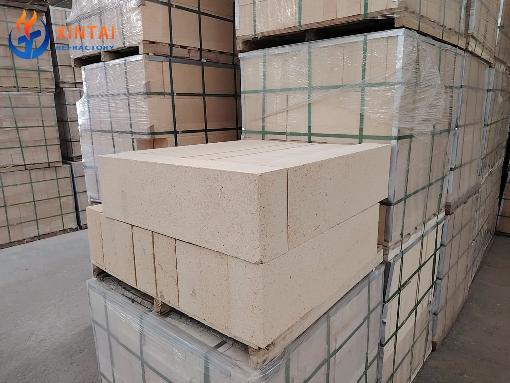
In high-temperature industries such as cement, metallurgy, and chemicals, the service life of refractory bricks in core equipment like rotary kilns and shaft furnaces directly determines production continuity, maintenance costs, and economic benefits.
Is Your Kiln Lining Falling Short of Its Expected Lifespan?
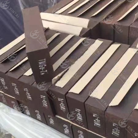
In the high-temperature battlefields of copper smelting, magnesia-chrome bricks serve as the guardians of furnace linings, enduring extreme environmental challenges. But why do the same refractory materials have varying service lives, with some suffering from "premature aging"?
Behind this phenomenon lies an "invisible hand of erosion."
Behind this phenomenon lies an "invisible hand of erosion."
The Mystery of "Premature Aging" in Magnesia-Chrome Bricks: The Invisible Hand of Erosion Accelerating Decay in Copper Smelting Furnaces!
The inside story of how one Chinese manufacturer is revolutionizing cooling stave reliability for steel producers across 30+ countries
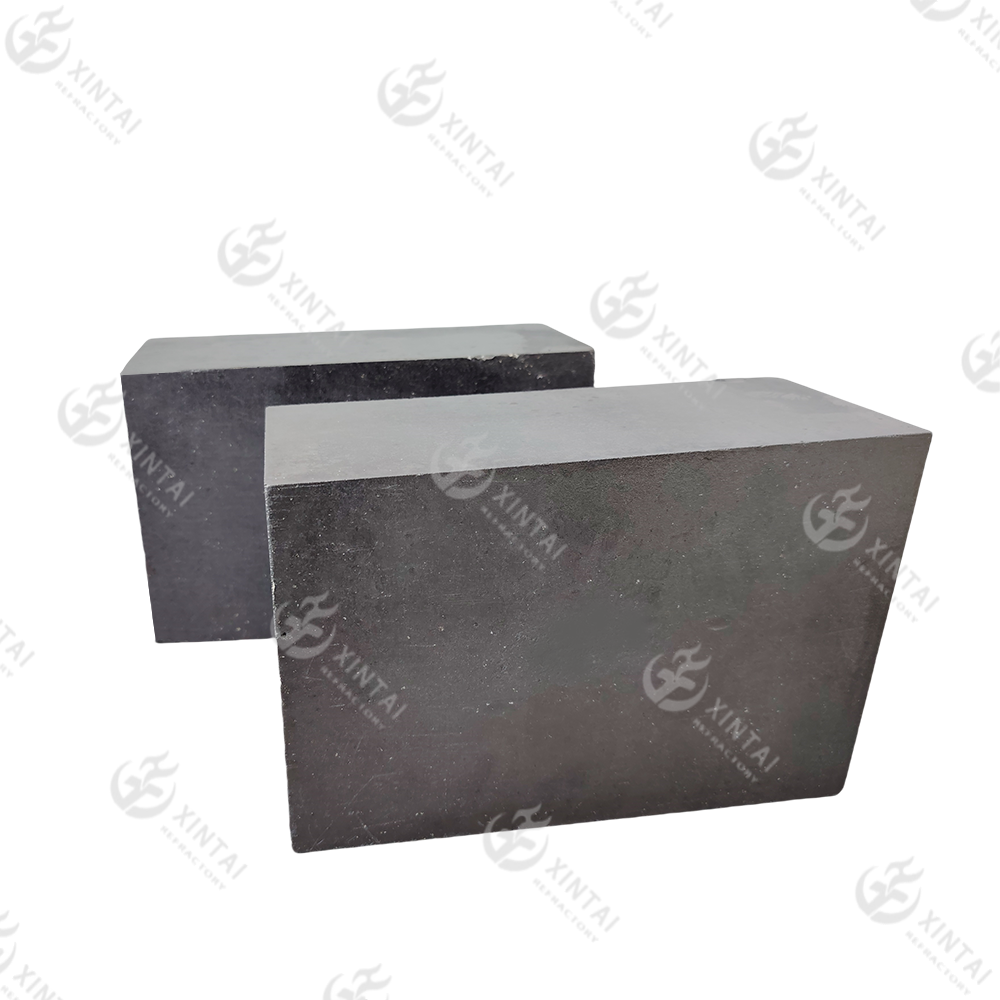
From Our Factory to Your Furnace: Why Henan Xintai's Silicon Carbide Bricks Are Transforming Blast Furnace Performance Worldwide
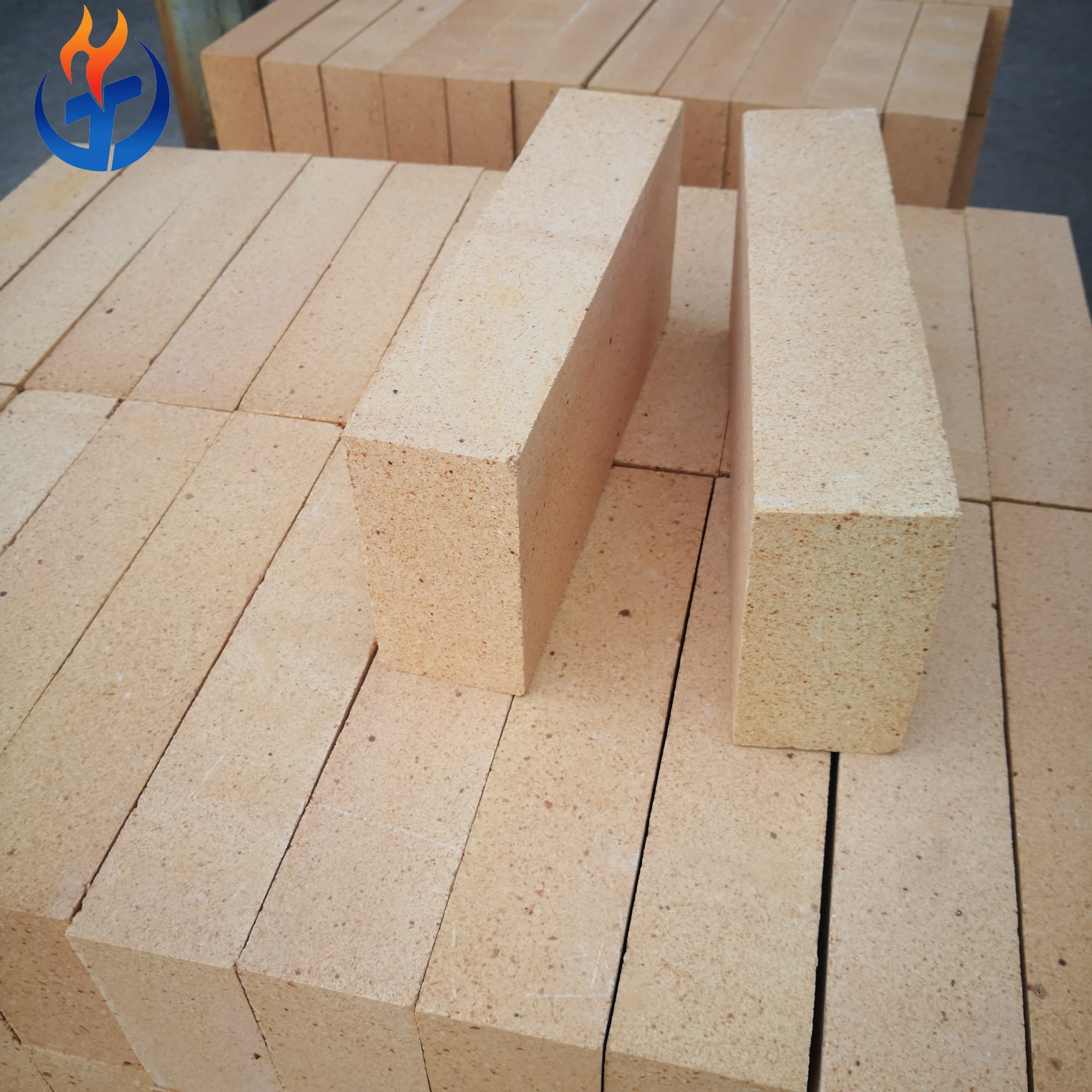
Refractory bricks are heat-proof ceramics that keep steel, glass, cement and petrochemical plants running above 1,000 °C. The global market is worth USD 24 B today and will reach 35 B by 2033, driven by Asian steel and cement plants.
The Ultimate Guide to Refractory Bricks: From Kilns to Cutting-Edge Furnaces